LED stage synchronization
Before presenting content on an LED stage with AR 51, you may want to synchronize AR 51’s coordinate system with the LED system.
This ensures a consistent origin across sessions and allows direct alignment with LED walls or floors.
Motivation
You want to present something on the LED stage and synchronize AR 51 with another system.
Examples include:
-
Use your body to control the content that is displayed on the LED wall/floor.
-
Ensuring the AR 51 origin is placed consistently in the same spot each time.
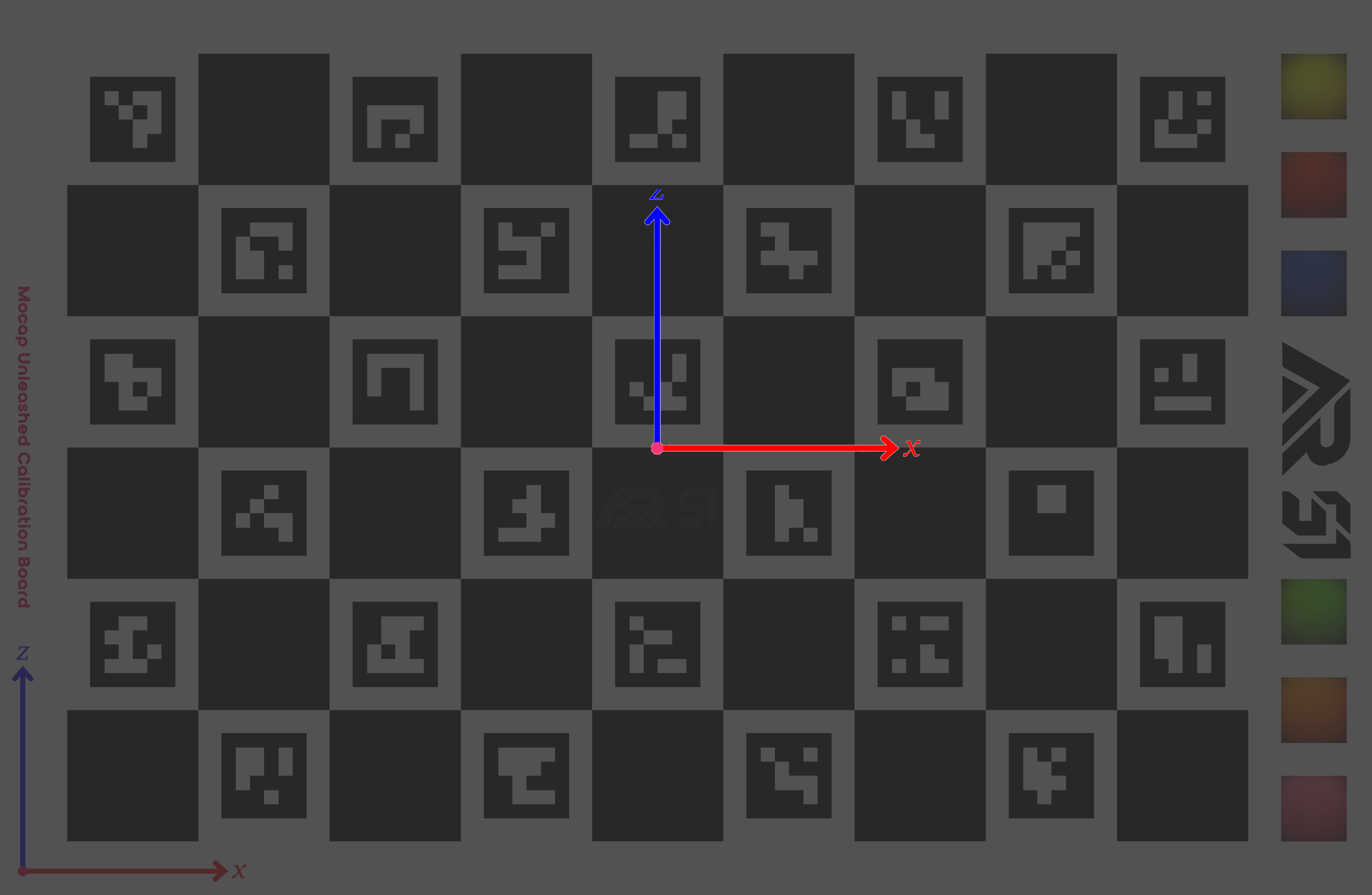
Using AR 51's Aruco Style checkerboard pattern
AR 51 Server Settings
-
In the AR 51 server settings:
-
Navigate to:
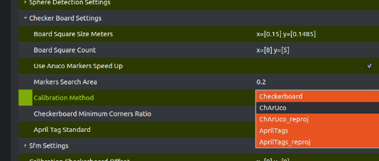
Camera Calibration Settings→Checker Board Settings→ Calibration Method -
Select Charuco from the dropdown menu.
-
- Navigate to:
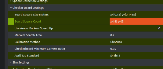
Camera Calibration Settings→Checker Board Settings→Board Square Count -
Set Board Square Count to reflect your number of corners on the board (8x5 in the attached file, note this is the corners not the actual squares count).
-
Save the server settings if you want this to persist.
-
Projecting the Checkerboard
To sync AR 51 coordinates with the LED stage:
-
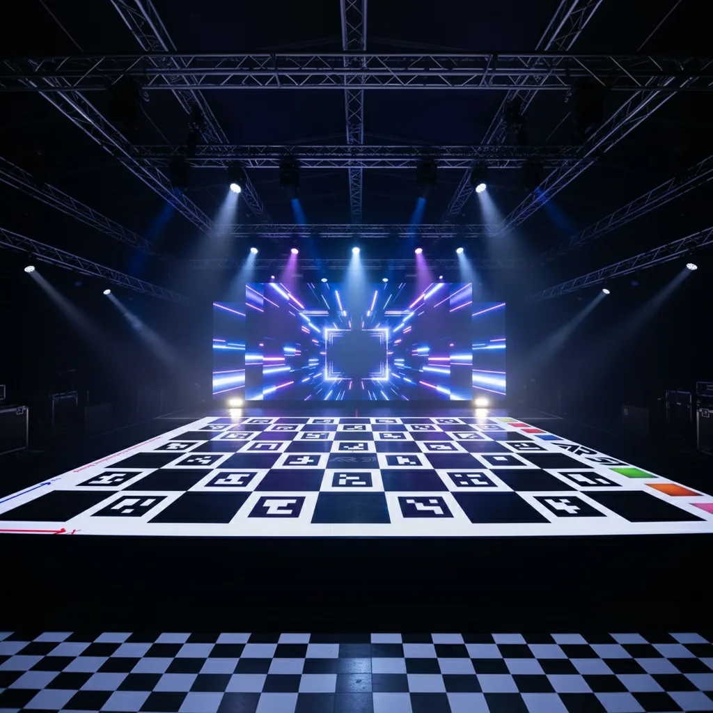
Project the provided checkerboard image onto the LED floor.
- Download the checkerboard image
-
The small mark at the center of the checkerboard indicates the AR 51 origin.
-
AR 51 uses a right-hand coordinate system where Y is up.
Using AprilTag Style checkerboard pattern
AR 51 Server Settings
-
In the AR 51 server settings:
-
Navigate to:
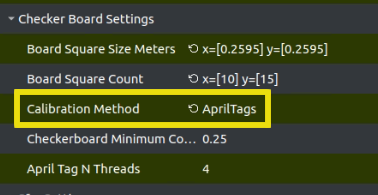
Camera Calibration Settings→Checker Board Settings→Calibration Method -
Select AprilTags from the dropdown menu.
-
Navigate to:
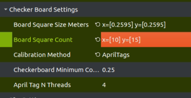
Camera Calibration Settings→Checker Board Settings→Board Square Count -
Set Board Square Count to reflect your number of squares on the board (10x15 in the attached file).
-
Save the server settings if you want this to persist.
-
Projecting the Checkerboard
To sync AR 51 coordinates with the LED stage:
-
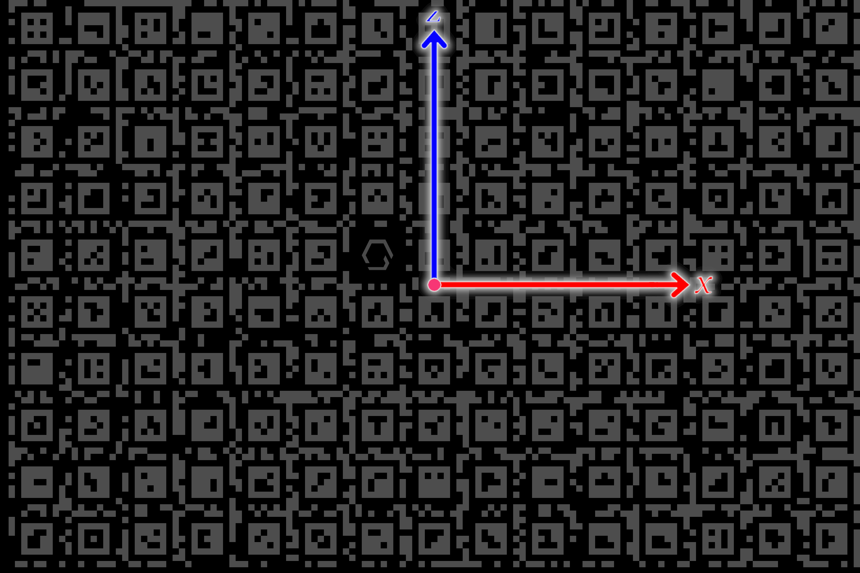
Project the provided april tags image onto the LED floor.
- Download the april tags checkerboard image
-
The center of the board is AR 51's system origin.
-
AR 51 uses a right-hand coordinate system where Y is up.
Rescaling the Checkerboard
- Measure the a calibration square in the "real world"
When you measure your "real world" checkerboard square make sure to measure the entire square - Not just the inner aruco area. You can also measure the pattern from side to side and divide by the number of squares for better accuracy.
| Standard Calibration Board | AprilTags Calibration Board |
|---|---|
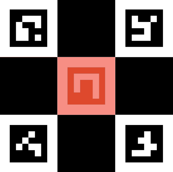 | 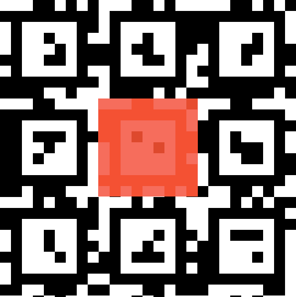 |
-
You may rescale the checkerboard, but it must be uniform so that each square remains a square.
-
In the AR 51 server settings:
-
Navigate to:
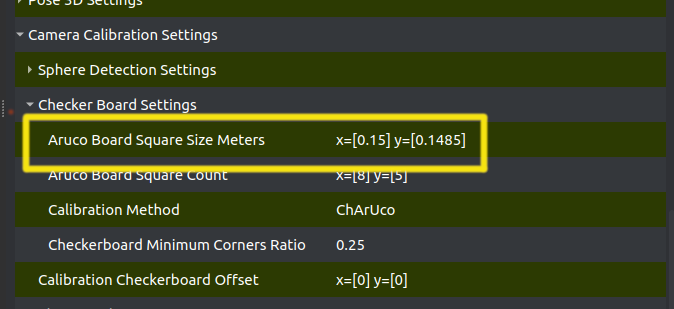
Camera Calibration Settings→Checker Board Settings→Aruco Board Square Size Meters -
Enter the real-world size of a checker square (in meters).
-
When you measure your "real world" checkerboard square make sure to measure the entire square - Not just the inner aruco area. You can also measure the pattern from side to side and divide by the number of squares for better accuracy.
Handling Coordinate Offsets
If the LED coordinate system is not centered on the stage (e.g., origin is in the upper-right corner), you can adjust using:
-
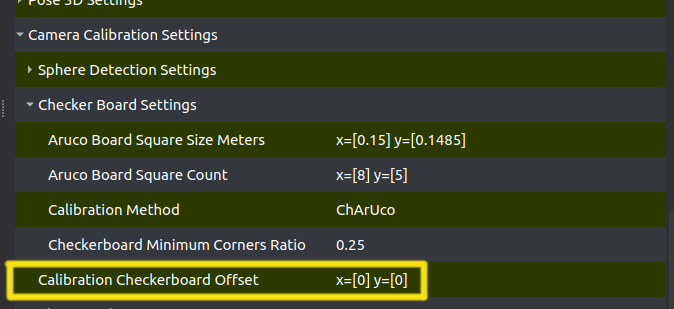
Camera Calibration Settings→ Calibration Checkerboard Offset -
Set the offset values so AR 51 matches the LED system’s origin.