Configure VLANs for Multiple Cameras on fs.com Switch
Table of contents
Goal
The goal of the steps is to group ports using Vlans on an fs.com switch. This allows for a virtual separation of devices on the same physical network. It can be used to split the cameras into different servers. Or, to switch them to different interface on the same computer.
Steps Before Using the Switch
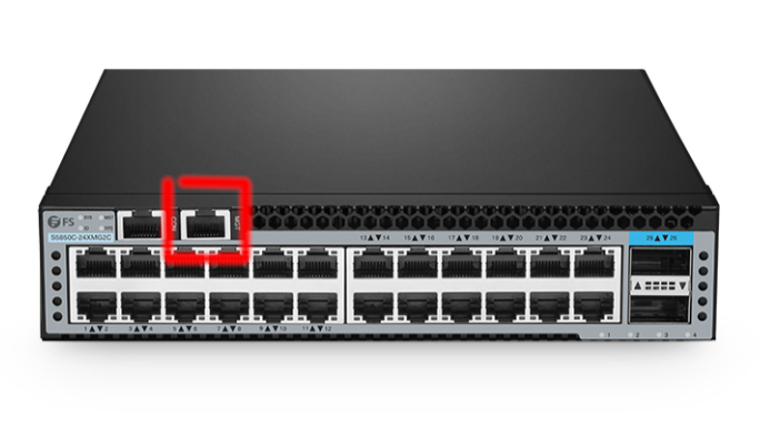
Step 1: Connect a Laptop for Configuration
- Use an ethernet cable to connect your laptop directly to the switch.
- The switch has a port marked MGT (management). Connect the cable there and to your laptop.
- Once configuration is done, this cable can be disconnected.
Step 2: Set Laptop IP Address
- By default, the switch uses IP 192.168.1.1.
- Set your laptop LAN IP to the same range (e.g., 192.168.1.10).
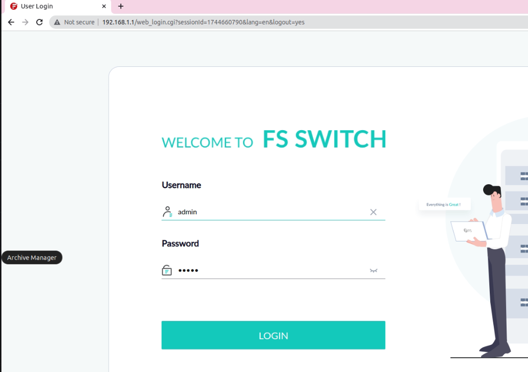
Step 3: Access the Web Management Interface
- Open a browser and navigate to 192.168.1.1.
- You should see the web-based management system of the switch.
Step 4: Login to Web Interface
- Use the following credentials:
- User: admin
- Password: admin
Switch Configuration via Terminal
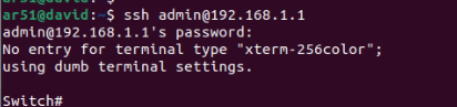
Step 6: Open a Terminal
- On your laptop, open PuTTY (or another SSH client).
- Connect to the switch:
ssh admin@192.168.1.1 - Password: admin
Step 7: Create VLANs for Camera-PC Groups
- Next, create VLANs so that each VLAN contains two camera ports and one PC port.
- Perform this action 8 times (one for each VLAN).
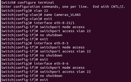
Run the following commands:
configure terminal
vlan Y
name Cameras_VLAN_Y
exit

interface eth-0-X
switchport mode access
switchport access vlan Y
no shutdown
exit
- Replace X and Y with the relevant port and VLAN ID.
- Repeat for all three interfaces in each VLAN (2 cameras + 1 PC).
Step 8: Verify VLAN Configuration
- Use the following command:
show vlan all
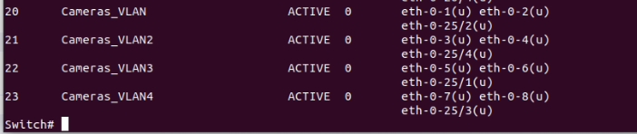
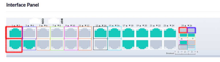
Summary
At the end of this process, you should have 8 VLANs defined. Each VLAN holds 3 connections: 1 to the PC and 2 to cameras. In the diagram below, each VLAN is shown with a distinct color.