Biomechanical Visualization & CSV Export in Mocap Studio
Mocap Studio includes built-in tools for visualizing joint angles and other biomechanical measurements directly inside the viewport.
You can also export these biomechanical values into CSV files, one file per character recorded, for use in analysis, research, and external workflows.
This page explains how to export biomechanical data and provides a complete reference for all biomechanical visualization settings available in Mocap Studio.
1. Recording and Exporting Biomechanical Data
1.1 Recording Panel Overview
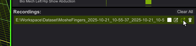
All recorded sessions appear in the Recordings panel.
Each recording can be played, renamed, deleted � and exported.
Below is the location of the Export button:
1.2 Exporting to CSV
Click the Export button on any recorded session.
This opens the Export dialog, where you select the desired file format:
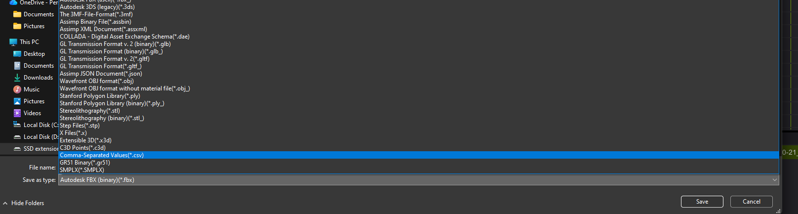
Export Behavior
- Mocap Studio exports one CSV file per character included in the recording.
- Each CSV contains all biomechanical values shown in the Biomech Visualization panel, sampled on every frame.
- Files are named based on the recording name, plus timestamp information.
CSV files can be used in:
- Excel, Google Sheets, Numbers
- Python / Pandas workflows
- MATLAB
- Data science and research pipelines
- Training machine learning models
- Motion analysis tools
2. Biomechanics Visualization Panel (Overview)
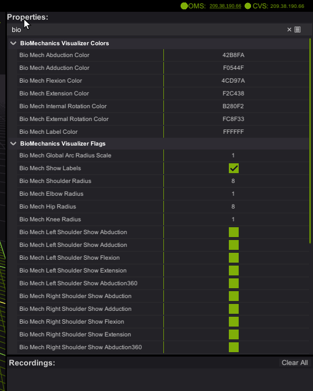
The Biomechanics panel appears in the Properties section of Mocap Studio.
It lets you control how joint biomechanics are displayed in the viewport, including arc visibility, colors, radius scaling, and per-joint toggles.
These visualization tools help you inspect angles and ranges of motion in real time.
3. Visualization Settings
3.1 Color Controls
These colors define the arcs drawn in the viewport.
Each represents a joint motion direction:
| Setting | Meaning |
|---|---|
| Abduction Color | Arm or leg moving away from the body midline. |
| Adduction Color | Arm or leg moving toward the body midline. |
| Flexion Color | Bending motion (e.g., lifting arm forward or bending the knee). |
| Extension Color | Straightening motion or backward motion. |
| Internal Rotation Color | Limb rotating toward the midline. |
| External Rotation Color | Limb rotating away from the midline. |
| Label Color | Color of numerical labels and text drawn near joints. |
These colors are also used in the CSV for column grouping and interpretation.
3.2 Global Display Options
| Setting | Description |
|---|---|
| Global Arc Radius Scale | Scales the size of all biomechanical arcs in the viewport. |
| Show Labels | Toggles on/off numerical joint labels showing angle values. |
3.3 Joint Radius Controls
Adjusts the size of arcs for each joint region:
| Joint | Control |
|---|---|
| Shoulders | Shoulder Radius |
| Elbows | Elbow Radius |
| Hips | Hip Radius |
| Knees | Knee Radius |
Increasing radius helps separate arcs visually when multiple joints are active.
4. Joint-Specific Visualization Flags
These flags allow you to choose which biomechanical measurements are shown per joint.
The screenshot below shows the full list of available toggles:
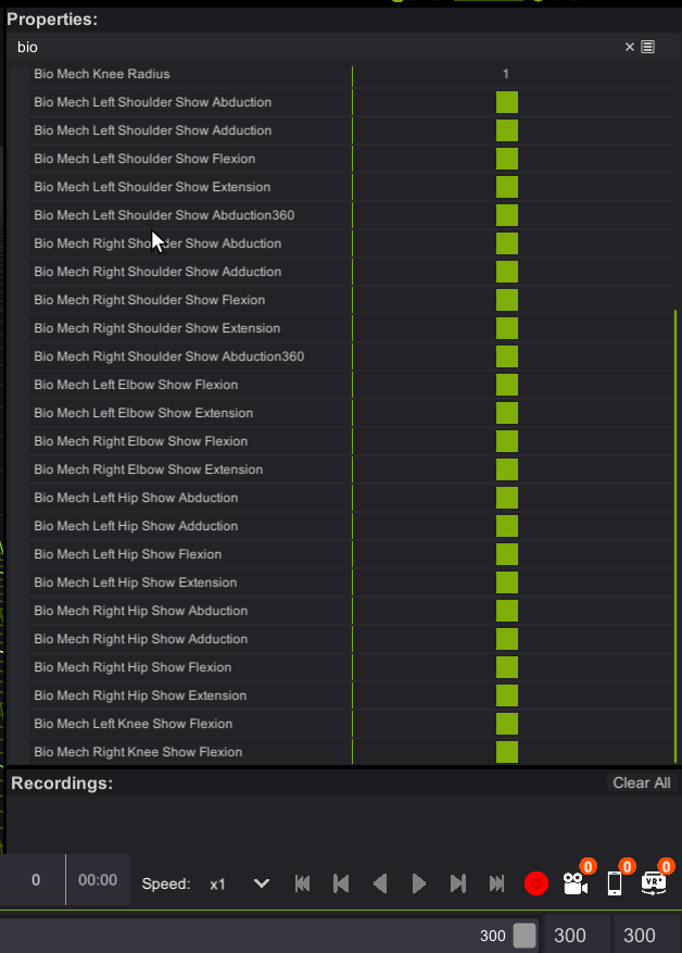
Each group has left/right side controls.
4.1 Shoulders
Left and Right Shoulder Flags:
- Show Abduction
- Show Adduction
- Show Flexion
- Show Extension
- Show Abduction360
Abduction360
Displays a full circular abduction range representation � useful for overhead and complex shoulder motion capture.
4.2 Elbows
Left and Right Elbow Flags:
- Show Flexion
- Show Extension
Elbow measurements typically represent hinge motion.
4.3 Hips
Left and Right Hip Flags:
- Show Abduction
- Show Adduction
- Show Flexion
- Show Extension
These appear around the pelvis and upper leg region.
4.4 Knees
Left and Right Knee Flags:
- Show Flexion
(Extension is implicitly visualized in opposite direction of flexion.)
5. CSV Export Structure (Technical Reference)
A CSV file is created per character and contains the following:
5.1 Rows
Each row represents one frame of captured motion.
5.2 Columns
Columns correspond to each enabled biomechanical measurement:
Example column names:
LeftShoulder_Abduction
LeftShoulder_Flexion
RightElbow_Flexion
RightHip_Adduction
LeftKnee_Flexion
...
5.3 Interpreting Values
- Values are expressed in degrees.
- Sign conventions match the arc directions in the viewport.
- If a visualization flag is disabled, the value may still appear in CSV (depending on feature set).
6. Tips & Best Practices (Technical)
- Use larger radius scales when arcs overlap visually between joints.
- When validating motion data, cross-check viewport values with CSV frames.
- Import CSV into Python with
pandas.read_csv()for advanced analysis. - In biomechanical research, combine CSV data with motion trajectories for joint torque estimation.
7. File Locations & Naming
- CSV files export to the folder you select in the Export dialog.
- Filenames follow:
RecordingName_CharacterName_YYYYMMDD_HHMMSS.csv - When exporting a session with multiple performers, expect multiple CSV files.
8. Summary
Mocap Studio�s biomechanical tools let you:
- Visualize joint angles in real time
- Export per-character CSV files for analysis
- Control exactly which angles and motions appear in the viewport
These tools support animation workflows, QA pipelines, and scientific analysis, making Mocap Studio a powerful solution for biomechanical capture.